block diagram
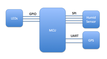
Let's build the block diagram from the critical chips that you have selected. Continuing the model rocket example, since we want to measure humidity, the humidity sensor is placed along with a GPS chip and some LEDs as shown below.
Although this block diagram is simple, it can be very helpful to ensure all of your goals are met. In this design, the micro controller (MCU) can sample the GPS and measure humidity, therefore, the location and humidity can be synced together which is ideal for the model. The light emitting diodes (LEDs) are not necessary but may be useful pre-launch if a green light to symbolize "Ready for Liftoff" while a red LED symbolizes a problem with the data collection circuitry.
In addition to the block diagram, a flow chart is also useful to make sure that the firmware you plan to implement will achieve your goals. Firmware is the program that is flashed onto the MCU to give the circuit "smarts" and decision-making ability. Without firmware, your circuit will just sit there burning up power!
In addition to the block diagram, a flow chart is also useful to make sure that the firmware you plan to implement will achieve your goals. Firmware is the program that is flashed onto the MCU to give the circuit "smarts" and decision-making ability. Without firmware, your circuit will just sit there burning up power!
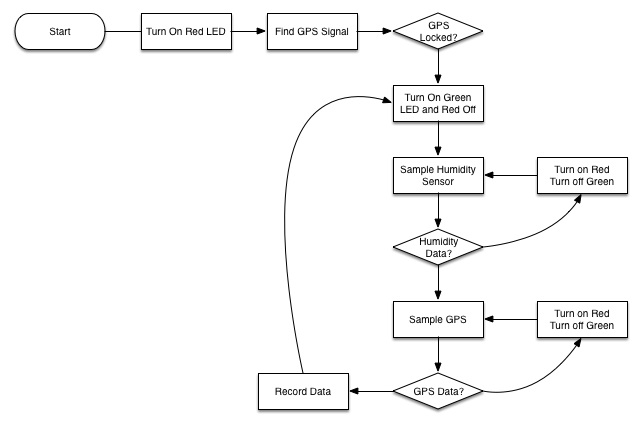
The flow chart should show the basic operation of the MCU from start to the ending loop. MCU's keep looping their instructions over and over so make sure you take this into account in your flow chart. In the model rocket example, the MCU starts by acquiring the ephemeris data for the GPS location. Once the GPS data is acquired, a loop begins to sense humidity data and check to make sure that a reading takes place. If it does not the red LED is turned on and the data is read again, otherwise, it moves on to the GPS location data and performs the same checks. If both humidity and GPS data is accessed, it is recorded and the process starts again.
This flow chart confirms that the blocks do all the commands that are required. There may be other pieces that need to be included in the schematic but can be ignored on the block diagram such as passive components like resistors, capacitors, buttons, or switches. You may also to include them in the block diagram for clarity... it is up to you! For example, the GPS block needs to have an antenna to access the satellites but it is not drawn in the block diagram.
At this point, you should be fairly confident that your goals will be achieved, so we will move forward with the schedule to find out when the project will be completed!


