Chip organization
A single PCB can have hundreds of chips and it can become very overwhelming quickly. In order to keep track of each chip and the respective data sheet, the designer should develop a master spreadsheet to summarize all the information. This is best done by creating a sheet for each chip that is to be used on the PCB with the chip layout, typical application schematic, pin numbers, layout footprint, and any other useful information that can be summarized. If you are going to be programming the MCU, it is helpful to create a separate spreadsheet for all the software information.
An example spreadsheet is shown below. If you are reading something on the data sheet that seems like it might be important, include it in your spreadsheet! General details are inputted into the spreadsheet such as manufacturer, distributer, part numbers, price, hyperlink, voltage, current. and temperature of operation. Almost every chip has this information and the rest of its information should be inputted as well.
Personally, I like to include screenshots from the datasheet to ensure that no mistakes are made during copying, especially, pin and pad information. The typical application schematic, pinout numbers, recommend footprint, and mechanical drawings are all essential information to a hardware designer during schematic and layout drawing. Including screenshots of these sections of the datasheet is highly recommended. By putting all this information in one location, building and revising chip selection and schematic is much easier than having to check each datasheet for information.
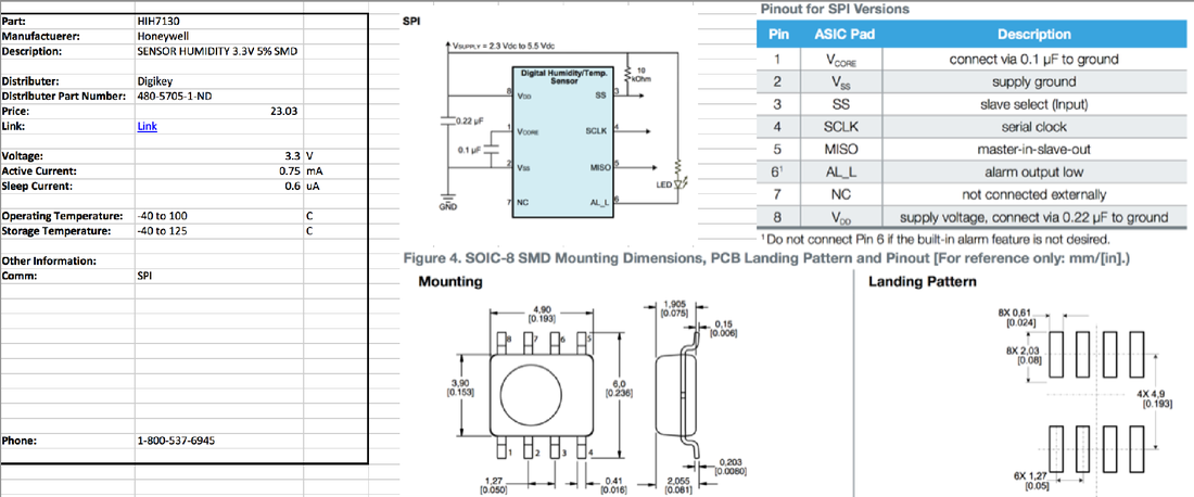
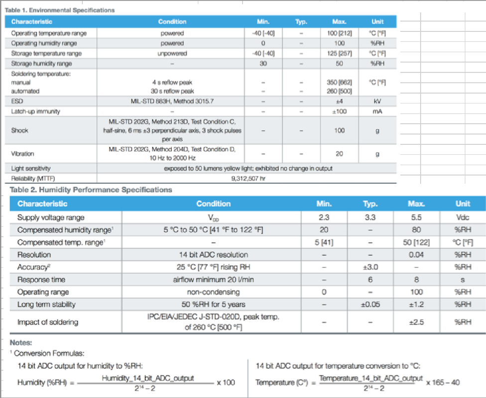
Other important charts, diagrams, and text should be included as well. See below a sample of the other information I included on the spreadsheet. Including this additional information makes the spreadsheet a "one stop shop" for all questions about your PCB being developed. If a part is changed, simply create a new sheet that can be added to the file. If a part is changed back (as it happens too often), the original sheet can be slide back into place.
A sheet for each one of your integrated circuits used on the PCB should be included in the spreadsheet. You may think that a regulator is too simple to be worth your time. Include it!!! If something those wrong on your board, you'll be thankful to have all the information on the chips in a single place.
