Pin Selection
After selecting a MCU, pin selection can be overwhelming. Many pins on microcontrollers can be used for more than one subsystem of the MCU. This is one of the greatest advantages of MCUs, but this ability also can make pin selection a difficult task. For a small MCU with 24 pins or less, this task can be done in your head or on paper fairly easier. But when moving to larger MCUs, I have found that using a spreadsheet can save you hours of hassling with different pin setups.
First, begin the spreadsheet with two columns: a general name for each pin and the pad number of the footprint of the MCU. If you are not familiar with the difference between a pin and a pad, let me clarify. A pin is the input/output of a device that is used in a schematic while the pad is the input/output used on the layout or actual printed circuit board. The pin in schematic is not always in the same location as the pad in the layout, so it is very important to keep track of this relationship.
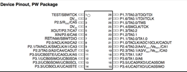
Here is an example of the MSP430F2132 that can all be found on the datasheet from here. The pins are indicated as Px.y and the pads are shown as the numbers on the actual chip with the dot representing where the first pin is. In addition to the pins, other applications of each pin are shown. For example, A0 is an analog to digital input, UCB0SIMO, UCB0SOMI, and UCB0CLK are for SPI communications, and ACLK can measure the internal auxiliary clock of the MCU.
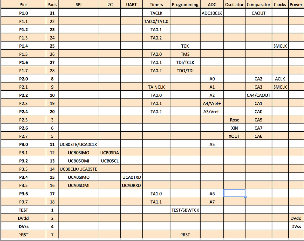
After the first two columns of the spreadsheet show the pin and pads numbers, the possible subsystems that can be used on each pin should be shown in each column. The spreadsheet shown below shows columns for each subsystem of the MCU and the rows show which pins and pads correlate to those subsystems. The intersection of the two has a name for the register or hardware inside the MCU that is being used. If you are not familiar with these or your MCU has different names (which is likely), use the datasheet to learn what each means.
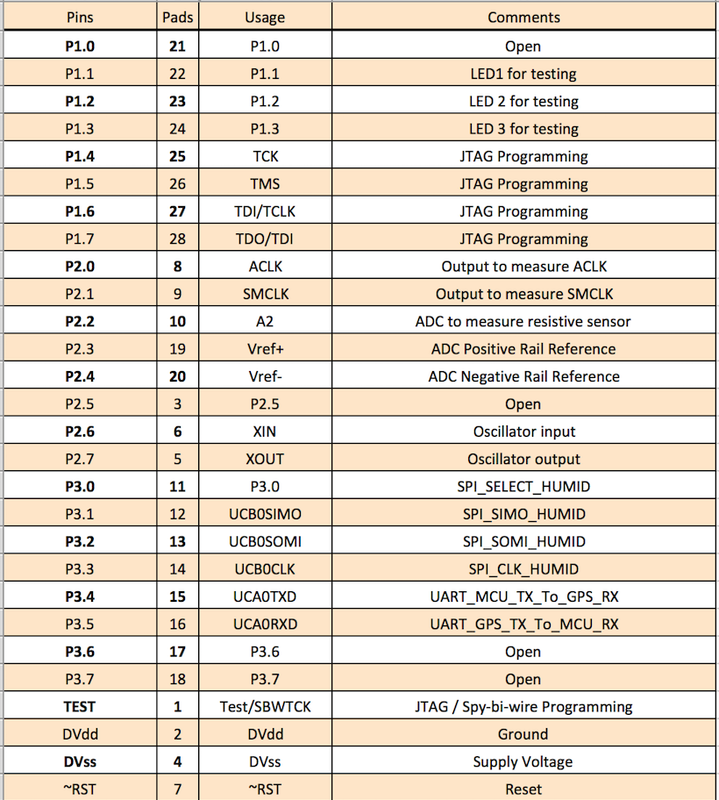
In the final two columns, you should add which subsystem you are going to use for each pin and comments about the connection. For this example, I selected the usage for each pin below. Since I needed SPI and UART to communicate with a humidity sensor and a GPS module, those pins were selected first from port 3. After that, an ADC was selected to measure the voltage output on a simple resistive touch sensor that varies voltage. The voltage is sampled by the ADC (A2). The ADC positive and negative rail can be set externally by regulators or dividers. Next, the programming pins were selected. Note that programming pins can be used as other operations but make debugging more difficult. JTAG is a 4 wire debugger that allows you to control the MCU line-by-line of code. Finally, 3 LEDs were added on GPIO pins. This is always a good technique for debugging and for helping a user understand what the MCU is doing. The ACLK and SMCLK are not needed but are helping to check that all the internal clocks are the frequencies you expect them to be. Using an external oscillator (XIN and XOUT) is ideal for SPI and I2C communications, because timing and sampling is very important. Internal oscillators on MCUs tend to be noisy and less accurate than externals. The last few pins not used for power and reset are left as open. These pins can be connected to empty pads so a very thin (30 awg) wire can be attached and soldered elsewhere.
At this point, your pins should have been selected and all the subsystems are understood. If not, go back and read your datasheet! The datasheet is your best friend when it comes to learning how the MCU works. Don't worry if you are unsure about some pins... leave notes to yourself. We are still in the planning phase and changes will happen.


